Balises are an integral part of the ERTMS/ETCS ensuring the transmission of data between the trackside and the onboard unit. There are two types of balise according to the data to transmit: the 'Fixed Data Balise' that transmit the same information hence the use of the word 'Fixed' as the location of the train and 'Transparent Data Balise' connected to the 'Lineside Electronic Unit' and transmits data according to the aspect of the signal. Other words can be used to describe the two types as switchable, fill, and infill. The use of both types is used for ERTMS/ETCS Level 1 while for Level 2 and Level 3 mostly the first type is only used for the train location.
 |
| Eurobalise |
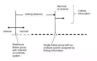
Linking
- The identity of the linked balise group,
- Where the location reference of the group has to be found.
- The accuracy of this location
- The direction with which the linked balise group will be passed over (nominal or reverse)
- The reaction required if a data consistency problem occurs with the expected balise group.
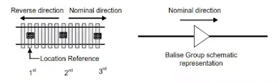
Group of Balise
A group of balise has to have at least one balise and 8 as a maximum, each one must store at least the internal number illustrating its position in the group, the number of balises in the associated group in addition to the group identity.
Each balise group has its own coordinate system and its orientation, to know whether the reverse and nominal direction, is defined as 'Group Balise Orientation'.
For the group of balise created of 2 or more balises, the first one is called 'location reference' and gives the origin of the coordinate system of its group
 |
| Orientation of a 2 to 8-balise-group |
For the single balise group (balise group composed of one balise), there are two scenarios according to ERTMS/ETCS Level. For level 1, the allocation of the coordinate system is done through the linking data and received from the previous balise group.
 |
| Orientation of a single balise group |
For ERTMS/ETCS Level 2 and Level 3, LRBG (Last Relevant Balise Group) is used as a common location reference between the ERTMS/ETCS onboard and trackside equipments in those levels.
If the ERTMS/ETCS on-board equipment cannot evaluate the orientation of the last balise group detected, being a single balise group, i.e. no linking information is available to identify the orientation of the co-ordinate system of this single balise group, the ERTMS/ETCS on-board equipment shall report its position by means of a position report based on two balise groups reporting the train position in reference to the LRBG and the “previous LRBG”
Rules
Distance
- 2.6 m from center to center, on lines with a Maximum Permitted Speed of 180 km/h
- 3.0 m from center to center, on lines with a Maximum Permitted Speed of 300 km/h
- 5.0 m from center to center, on lines with a Maximum Permitted Speed of 500 km/h.
 |
| Minimum Distance Between Eurobalises |
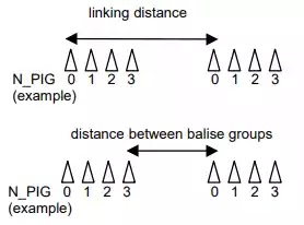 |
| Linking and Balise Group distance |
Installation
The maximum distance between two consecutive balises within the same group shall be 12 m from reference mark to reference mark.
With regards to balises at a signal containing switched information any balise located in rear of the operational stopping location shall not be located further than 0.7m in rear of the operational stopping location.
 |
| Maximum distance between a balise and the stopping point |
If the transition from one train detection section to the following one affects the information transmitted by a switchable balise, this switchable balise shall be placed at least 13.8 m in rear of the location where the detection device of the next section may start detecting the train.
 |
| Minimum distance between a balise of a balise group and limit of train detection section |
Sources:
SUBSET-026-3: System Requirements Specification - Chapter 3 - Principles
SUBSET-023: Glossary of Terms and Abbreviations
SUBSET-040: Dimensioning and Engineering rules
SUBSET-036: FFFIS for Eurobalise
0 Comments
Post a Comment