This article aims to give an overview of the European Rail Traffic Management System (ERTMS) through History, Statistics, European Deployment Plan, FRMCS, GSM-R alternatives, CCS TSI, Braking Curves, Baselines, Baselines compatibility, Levels, Modes, and case studies.
Table of Contents
- Definition and History
- ERTMS Deployment statistics
- ERTMS European Deployment Plan (EDP)
- ERTMS Architecture, CCS TSI, and its interfaces
- ERTMS Subsystems
- FRMCS, The Successor of GSM-R
- Is it possible to use other radio communication systems than GSM-R? ERTMS
- Levels ERTMS Modes
- ETCS Braking Curves
- ERTMS/ETCS Baselines & Backwards/Forwards compatibility
- The Elizabeth Line: one of the most challenging Signalling projects
For this article, you may need to refer to SUBSET-023, the Glossary of terms and abbreviations. (link: https://bit.ly/2Wc6dja )
1. Definition and History
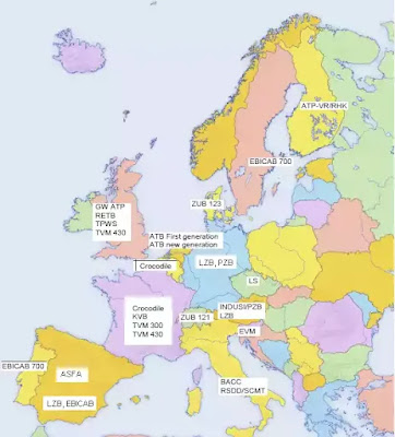 |
| European ATP systems |
Normally these systems were not compatible with each other and thus crossing a signalling area border meant that trains needed to implement several on-board ATP devices, each of which was self-functioning. Due to the increasing international rail services, a harmonised ATP system is needed for the European context. Thus, the aim of the ERTMS was (and is) to gradually replace the different national ATP systems in European countries[2].
2. ERTMS Deployment statistics
According to the last update by UNISIG (Union Industry of Signalling), by September 2020, half of the ERTMS/ETCS Level 1 and Level 2 tracks are and 31% of contracted vehicles are outside Europe: these countries have also shown their taste and conviction for ERTMS deployment, committing to more than 12 000 vehicles and more than 30 000km of tracks. [3]
 |
| ERTMS worldwide statistics |
 |
| ERTMS worldwide deployment evolution |
3. ERTMS European Deployment Plan
The guidelines for the Trans-European Transport Networks (TEN-T) establish ERTMS as one of the requirements for railway infrastructure and sets out a deadline for its deployment on the core network by 2030 and on the entire network by 2050. Building on this, the ERTMS European Deployment Plan (EDP), adopted by the European Commission in January 2017, sets out deadlines for deploying ERTMS on some sections of the core network corridors for the period 2017-2023.
4. ERTMS Architecture, CCS TSI, and its interfaces
 |
| ERTMS/ETCS references architecture |
CCS TSI Annex A – Mandatory specifications - Set of specifications 3 (ETCS B3 R2 GSM-R B1):
- SUBSET-034: Train interface
- ERA_ERTMS_015560: ETCS Driver Machine Interface
- SUBSET-027: Juridical Recording
- SUBSET-035: Specific Transmission Module FFFIS
- SUBSET-056: STM FFFIS Safe time layer
- SUBSET-057: STM FFFIS Safe link layer
- SUBSET-058: FFFIS STM Application layer
- SUBSET-101: Interface "K" Specification
- SUBSET-100: Interface "G" Specification
- SUBSET-036: FFFIS for Eurobalise
- SUBSET-044: FFFIS for Euroloop
- SUBSET-037: EuroRadio FIS A11T6001: (MORANE) Radio Transmission FFFIS for EuroRadio
- SUBSET-047: Trackside-Trainborne FIS for Radio infill
- SUBSET-114: KMC-ETCS Entity Off-line KM FIS
- SUBSET-137: On-line Key Management FFFIS
- SUBSET-038: Offline Key Management FIS
- SUBSET-039: FIS for RBC/RBC handover
- SUBSET-098: RBC-RBC Safe Communication Interface
In addition to the specifications above, there is also 'Informative specifications' that are available also for download: https://bit.ly/3mnvFNz
5. ERTMS Subsystems
Due to the nature of the required functions, the ERTMS/ETCS system will have to be partly on the trackside and partly on board the trains.
NOTE: Interlocking is not part of ERTMS
Trackside[5]
Depending on the application level, the trackside subsystem can be composed of:
- Balise: is a transmission device that can send telegrams to the on-board subsystem
- Lineside Electronic Unit (LEU) : The LEUs are electronic devices, that generate telegrams to be sent by balises, on basis of information received from external trackside systems.
- Radio communication network (GSM-R): The GSM-R radio communication network is used for the bi-directional exchange of messages between on-board subsystems and RBC or radio infill units.
- Radio Block Centre (RBC): is a computer-based system that elaborates messages to be sent to the train on basis of information received from external trackside systems and on basis of information exchanged with the on-board subsystems
- Euroloop: The Euroloop subsystem operates on Level 1 lines, providing signalling information in advance as regard to the next main signal in the train running direction.
- Radio infill unit: operates on Level 1 lines, providing signalling information in advance as regard to the next main signal in the train running direction.
- Key Management Centre (KMC): The role of the KMC is to manage the cryptographic keys, which are used to secure the EURORADIO communications between the ERTMS/ETCS entities (ERTMS/ETCS on-board equipments, RBCs and RIUs)
- Public Key Infrastructure (PKI): The role of the PKI is to manage and distribute digital certificates, so as to allow a secure on-line distribution of cryptographic keys between KMCs and from a KMC to the ERTMS/ETCS entities (ERTMS/ETCS on-board equipments, RBCs and RIUs).
Onboard[6]
Depending on the application level, the on-board subsystem can be composed of:
- Euro Vital Computer (EVC): is the core of the ETCS onboard device. It is part of the Automatic Train Protection logic and is the unit with which all the other train functions interact, such as the odometer or the GSM-R data reception.
- Driver Machine Interface (DMI): the interface between the driver and the ETCS. In most cases, it is an LCD touch screen panel for control and indication functions, allowing the driver to enter the required input data into the system and to visualise the output data.
- Train Interface Unit (TIU): is the interface that allows the ETCS to exchange information and issue commands to the rolling stock.
- Juridical Recording Unit (JRU): provides ‘black box’ functions, i.e. it stores the most important data and variables from train journeys, allowing later analysis.
- Balise Transmission Module (BTM): The BTM is a module inside the ETCS onboard equipment for intermittent transmission from track to train, which processes signals received from the onboard antenna and retrieves data messages from a Eurobalise.
- Loop Transmission Module (LTM): The LTM is an optional module inside the ETCS onboard equipment for transmission from track and train, which processes signals received from the onboard antenna and retrieves data messages from a Euroloop.
- Onboard radio communication system (Euroradio): The GSM-R onboard radio system is used for the bi-directional exchange of messages between the onboard subsystem and RBC or radio infill unit. The onboard Euroradio is a module inside the ETCS onboard equipment for exchanging messages between track and train, which processes signals received from the onboard antenna and retrieves application data messages from the RBC or the RIU.
- Odometry system: The odometer is responsible for calculating the distance run by the train, typically consisting of redundant tachometry and radar, able to calculate distance, speed and acceleration.
- Specific Transmission Module (STM): The STM is a device that allows the ETCS onboard equipment to be interfaced with the onboard part of an existing National Train Control system. It will enable smooth transitions from/to the national system(s) and gives access to some ETCS onboard resources (e.g. DMI). Depending on its functionality and the desired configuration, the national system can be addressed either via an STM using the standard interface or via another national solution.
6. FRMCS, The Successor of GSM-R
GSM-R is approaching obsolescence. The GSM-R suppliers have committed to support this system until 2030, and possibly beyond. There is, consequently, a need to replace GSM-R, an issue which is critical in Europe where railways have implemented GSM-R on more than 100,000km of lines, in a fully interoperable way.
Since 2010, UIC-member railway organisations have been discussing a successor to GSM-R. The work on specifying the GSM-R successor, which is the Future Railway Mobile Communication Systems (FRMCS), was launched by the International Union of Railways (UIC) as a project in 2014[7].
 |
| FRMCS TSI |
[8] FRMCS will be based on 3GPP building blocks, gaps will be covered by ETSI specifications. The system will have an FRS and an SRS, to provide the necessary means to operate the FRMCS networks and to guarantee their interoperability in the context of cross border operations. The FRS and the SRS will complete the FRMCS system and will be the base in the CCS TSI for the Train-Radio and ETCS critical applications. The UIC FRMCS planning includes three steps:
- Deliver the first stable version of specifications and obtain frequencies
- Prepare and deliver the FRMCS demonstrator, based on the stable specifications and 3GPP R16 products
- Prepare and deliver a FRMCS European trial, based on updated specifications and 3GPP R17 products.
 |
| FRMCS Planning |
7. Is it possible to use other radio communication systems than GSM-R?
Tetra
Australia: Siemens Mobility and DAMM Cellular Systems have together successfully implemented and tested an open and interoperable Tetra packet data solution which complies with the demands for ETCS Level 2. The tests were mainly focused on bandwidth requirements and the reliability of data delivery. They were performed according to UNISIG Subset-093 (PS version) – the communication requirement specification for ETCS describing the worst-case conditions for ETCS communication.[9]
LTE
8. ERTMS Levels[5]
ERTMS/ETCS Level 0
The train is equipped with ERTMS/ETCS operating on a line not equipped with any train control system (ERTMS/ETCS or national system) or on a line equipped with ERTMS/ETCS and/or national system(s) but operation under their supervision is currently not possible.
 |
| ERTMS/ETCS Level 0 |
ERTMS/ETCS Level NTC
 |
| ERTMS/ETCS Level NTC |
ERTMS/ETCS Level 1
With or without infill transmission, train equipped with ERTMS/ETCS operating on a line equipped with Eurobalises and optionally Euroloop or Radio infill
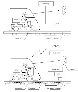 |
| ERTMS/ETCS Level 1 |
ERTMS/ETCS Level 2
The train is equipped with ERTMS/ETCS operating on a line controlled by a Radio Block Centre and equipped with Eurobalises and Euroradio, with train position and train integrity proving performed by the trackside.
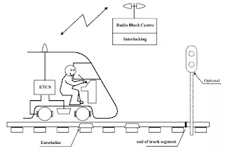 |
| ERTMS/ETCS Level 2 |
ERTMS/ETCS Level 3
Similar to level 2 but with train position and train integrity supervision based on information received from the train.
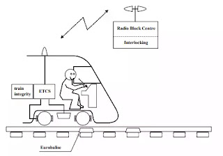 |
| ERTMS/ETCS Level 3 |
9. ERTMS Modes
Operation modes can be defined as different conditions required for managing different situations regarding the status of the trackside and the train itself. Unlike the ETCS levels (associated with train-trackside communication), ETCS modes are related to the operational circumstances of the line or the onboard equipment status.[13]
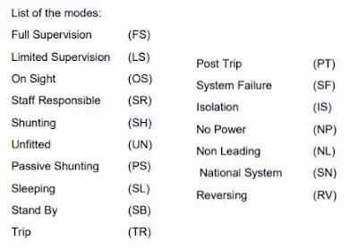 |
| ETCS modes |
- ISOLATION: In Isolation mode, the ERTMS/ETCS on-board equipment shall be physically isolated from the brakes and can be isolated from other on-board equipments/systems depending on the specific on-board implementation. Used in all levels: Level 0, level 1, level 2, level 3 and level NTC[14].
- NO POWER: When the ERTMS/ETCS on-board equipment is not powered, the equipment is in the No Power mode. Used in all levels: Level 0, level 1, level 2, level 3 and level NTC.
- SYSTEM FAILURE: The ERTMS/ETCS on-board equipment shall switch to the System Failure mode in case of a fault, which affects safety. Used in all levels: Level 0, level 1, level 2, level 3 and level NTC.
- SLEEPING: The Sleeping mode is defined to manage the ERTMS/ETCS on-board equipment of a slave engine that is remote controlled. Used in all levels: Level 0, level 1, level 2, level 3 and level NTC
- STAND BY: The Stand-By mode is a default mode and cannot be selected by the driver. Used in all levels: Level 0, level 1, level 2, level 3 and level NTC
- SHUNTING: The purpose of the Shunting mode is to enable shunting movements. Used in level 0, NTC, 1, 2 and 3.
- FULL SUPERVISION: The ERTMS/ETCS on-board equipment shall be in the Full Supervision mode when all train and track data, which is required for a complete supervision of the train, is available on board. Used in level 1, 2 and 3.
- UNFITTED: The Unfitted mode is used to allow train movements in either; areas that are equipped neither with ERTMS/ETCS track-side equipment nor with national train control system or areas that are equipped with ERTMS/ETCS trackside equipment and/or national train control system(s), but operation under their supervision is currently not possible. Used in level 0.
- STAFF RESPONSIBLE: The Staff Responsible mode allows the driver to move the train under his own responsibility in an ERTMS/ETCS equipped area. This mode is used when the system does not know the route. Used in level 1, 2 and 3.
- ON SIGHT: The On Sight mode enables the train to enter into a track section that could be already occupied by another train, or obstructed by any kind of obstacle. This mode cannot be selected by the driver, but shall be entered automatically when commanded by trackside and all necessary conditions are fulfilled. Used in level 1, 2 and 3.
- NON LEADING: The Non-Leading mode is defined to manage the ERTMS/ETCS on-board equipment of a slave engine that is NOT electrically coupled to the leading engine (and so, not remote controlled) but has its own driver. Used in all levels: Level 0, level 1, level 2, level 3 and level NTC.
- National System (SN) mode: In SN mode, according to the specific on-board implementation, the National System may access the following resources via the ERTMS/ETCS on-board equipment: DMI, Juridical Recording interface, odometer, train interface and brakes. This can be achieved through the STM interface. Used in level NTC.
- REVERSING: The Reversing mode allows the driver to change the direction of movement of the train and drive from the same cab, i.e. the train orientation remains unchanged. This is possible only in areas so marked by trackside. Used in level 1, 2, 3.
- LIMITED SUPERVISION: The Limited Supervision mode enables the train to be operated in areas where trackside information can be supplied to realise background supervision of the train. Limited supervision can not be selected by the driver, but shall be entered automatically when commanded by trackside and all necessary conditions are fulfilled. Used in levels 1, 2 and 3.
- PASSIVE SHUNTING: The Passive Shunting mode is defined to manage the ERTMS/ETCS on-board equipment of a slave engine (NOT remote controlled, but mechanically coupled to the leading engine), being part of a shunting consist. This mode can also be used to carry on a shunting movement with a single engine fitted with one on-board equipment and two cabs, when the driver has to change the driving cab. Used in all levels: Level 0, level 1, level 2, level 3 and level NTC.
10. ETCS Braking Curves[15]
A CCS system does not brake, i.e. it is not responsible for the braking system of the train, which will do the actual job. ETCS (and also some elaborated legacy CCS systems) supervises both the position and speed of the train to ensure they continuously remain within the allowed speed and distance limits, and -if necessary- it will command the intervention of the braking system to avoid any risk of the train exceeding those limits.
To do so the ETCS onboard computer must predict the decrease of the train speed in the future, from a mathematical model of the train braking dynamics and of the track characteristics ahead. This prediction of the speed decrease versus distance is called a braking curve.
The braking curve related to the speed decrease due to the emergency brake is called EBD (Emergency Brake Deceleration) curve. Each specific target location (corresponding either to a speed reduction or to a stop location) given by the ETCS trackside is used by the ETCS on-board to compute a fully deterministic EBD curve, which depends on both train and track characteristics. The shape of the EBD curve, for a given piece of track, will therefore vary according to the type of rolling stock: the less the emergency braking system is efficient, the flatter the EBD curve will be.
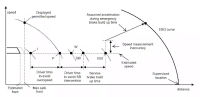 |
| ETCS braking curve |
The ETCS on-board calculates in real time other supervision limits: Indication (I), Permitted speed (P), Warning (W) and Service Brake Intervention (SBI) (only if the ETCS on-board is designed to command itself the service brake). They consist of locations that, when crossed by the train, will trigger some information to be given to the driver through appropriate graphics, colours and sounds on the Driver Machine Interface. These locations are defined in order to:
- For the “I” supervision limit: leave the driver enough time to act on the service brake so that the train does not overpass the Permitted speed, when this latter will start to decrease. Without the indication it would not be possible for the driver to perform a transition from ceiling speed supervision to the target speed supervision without overpassing the Permitted speed
- For the “P” supervision limit: in case of overspeed, to leave the driver an additional time to act on the service brake so that the train will not overpass the point beyond which ETCS will trigger the command of the brakes.
- For the “W” supervision limit, to give an additional audible warning after the Permitted speed has been overpassed.
- For the “SBI” supervision limit, to take into account the service brake build up time so that the EBI supervision limit is not reached after the command by ETCS of the full service brake effort. The SBI supervision limit is facultative and can be implemented on-board the train in order to avoid too frequent emergency braking, which can be damaging for both the rolling stock and the track.
11. ERTMS/ETCS Baselines & Backwards/Forwards compatibility
Baseline definition
The baseline is a stable kernel in terms of system functionality, performance and other non-functional characteristics. Any system needs to evolve, and new functions and corrections might be needed.
“Baseline 2’’ is the first set of requirements, considered as interoperable, and to be adopted at European level.
“Baseline 3” is a controlled evolution of Baseline 2 that includes new additional functions and backward compatibility with Baseline 2[16].
Backward and forward compatibility of ETCS baselines
A first baseline compatibility assessment undertaken by the sector (UNIFE/UNISIG and ERTMS Users Group) has checked the compatibility between ETCS baseline 3 MR1 and ETCS baseline 2 (release 230d).
Within the scope of this assessment and provided that its recommendations are taken into account, the ETCS baseline 3 MR1 is backward compatible with ETCS baseline 2.
A second baseline compatibility assessment has checked that:
- ETCS baseline 3 R2 is fully backward/forward compatible with ETCS baseline 3 MR1.
- Both the backward compatibility between ETCS baseline 3 R2 vehicles and ETCS Baseline 2 trackside and the compatibility between ETCS baseline 3 R2 trackside operated with system version X=1 (i.e. ETCS Baseline 3 R2 trackside using only baseline 2 functions) and ETCS baseline 2 vehicles.
 |
| ETCS baselines compatibility |
The second baseline compatibility assessment also includes the analysis of the compatibility between trackside and onboard both within ETCS baseline 3 MR1 and within ETCS baseline 2, in the light of the problem description of the Change Requests included in ETCS baseline 3 R2.
This second baseline compatibility assessment confirms that the ETCS baseline 3 R2 is fully backwards and forwards compatible with the ETCS baseline 3 MR1, i.e. that ETCS baseline 3 R2 vehicles can run a normal service on ETCS baseline 3 MR1 trackside and ETCS baseline 3 MR1 vehicles can run a normal service on ETCS baseline 3 R2 trackside[1].
12. The Elizabeth Line: one of the most challenging Signalling projects
Crossrail is building the Elizabeth Line – a new railway in London that runs between Reading and Heathrow in the west to Shenfield in Essex and Abbey Wood in south east London. The new railway will use three distinct signaling systems, AWS/TPWS in the east, CBTC in the new central section and ETCS in the west.[17]
 |
| Elizabeth line Map and signalling systems |
In addition to the different signalling systems, the control of the Crossrail route will be split across three control centres. On the GW main line, this is from the Thames Valley Signalling Centre at Didcot. The Crossrail core, including to Abbey Wood, will have a new control centre contained within Network Rail’s Rail Operating Centre (ROC) at Romford. The GE line, which is currently controlled from Liverpool Street IECC, will eventually transfer to the Romford ROC as well.
 |
| Elizabeth line - DMI |
As can be imagined, testing such a complex signalling arrangement could never be progressed on site. The solution was to start with laboratory testing, involving several labs in different parts of the world including Bombardier in Stockholm and Delhi, Siemens in Paris, Braunschweig and Chippenham, Mors Smitt (part of Wabtec) in Crewe and Burton, Alstom for ETCS interoperability and a further lab for Customer Information integration.[18]
 |
| Elizabeth line - Onboard subsystem |
Sources
[1] European Union Agency for Railways - European Rail Traffic Management System (ERTMS) Link: https://bit.ly/3z4DGdU
[2] European Commission - ERTMS - History of ERTMS Link: https://bit.ly/3B33Yhf
[3] UNISIG - Deployment Statistics Link: https://bit.ly/3CXw5jP
[4] Rail Tech - EU Commission: deployment ERTMS is behind on schedule Link: https://bit.ly/3klx6d4
[5] SUBSET-026-2: System Requirements Specification - Chapter 2 - Basic System Description Link: https://bit.ly/3CZUaqh (index 04)
[6] European Commission - Rail - Subsystems and Constituents of the ERTMS Link: https://bit.ly/2W9Wg6m
[7] Global Railway Review - FRMCS: More than just a successive replacement for GSM-R Link: https://bit.ly/3B2pens
[8] European Union Agency for Railways - FRMCS Definition, Specification and Standardization Activities Link: https://bit.ly/3AZVLKM
[9] TCCA - SIEMENS and DAMM complete testing of ETCS over Tetra Packet Data Link: https://bit.ly/381yjQO
[10] Railway Gazette Group - ETCS over Tetra certified Link: https://bit.ly/3zmRKQl
[11] Teltronic - Teltronic’s TETRA solution, certified to support ETCS Link: https://bit.ly/3sGVjhI
[12] Alstom - Press Release Link: https://bit.ly/3D88gG1
[13] European Commission - Rail - ETCS Levels and Modes Link: https://bit.ly/3z3QvVT
[14] SUBSET-026-4: System Requirements Specification - Chapter 4 - Modes and Transitions Link: https://bit.ly/3CZUaqh Index (04)
[15] ERA_ERTMS_040026 - INTRODUCTION TO ETCS BRAKING CURVES Link: https://bit.ly/3ml1JSo
[16] European Commission - Rail - ERTMS - FAQ on ERTMS Link: https://bit.ly/3mnUc5p
[17] ERTMS Solutions - ERTMSCAMCORDER TO BE USED ON AS AN INTEGRATED ONSITE TESTING SOLUTION ON THE CROSSRAIL PROJECT Link: https://bit.ly/3ze8GZ2
[18] Rail Engineer - Crossrail’s Signalling Challenge Link: https://bit.ly/3D0JCqG
0 Comments
Post a Comment